INSTRUMENTATION & PROCESS CONTROL
Click on images to enlarge
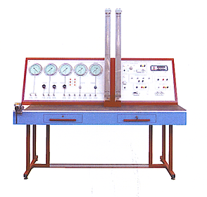
ELECTRICAL, ELECTRONIC & PNEUMATIC CALIBRATION BENCH
General
The equipment consists of a bench, a console and a set of instruments, designed to give the learner full exposure in the maintenance and calibration of the pneumatic and electronic instrumentation which form the basis of process control.
Training Program
The equipment provides practical experience
in calibrating
· Pressure gauges
· Pressure switches
· Thermostats
· Pneumatic differential pressure transmitters
· Electronic differential pressure transmitters
· Pneumatic pressure transmitters
· Electronic pressure transmitters
· Pneumatic indicators
· Electronic indicators
· Electronic indicators/controllers
· Pneumatic level transmitters
· Electronic level transmitters
· Pneumatic recorders
· Electronic recorders
· Pneumatic indicators controllers
· Hydrostatic thrust level transmitters
· Capacitive probe level transmitters
· Pneumatic valves
· Positioners
Services
220/240V L plus ground
Air supply 10bars max
Technical Specification
Painted carbon steel structure
4 precision pressure gauges, -1 - 0, 0 - 1.6, 0 - 4 and 0-10, class 0.25%
1 manual control station, complete with precision pressure gauge
3 precision pressure reducers
12 pressure outputs
2 differential pressure glass manometers, height = 1000 mm,
stainless steel sleeve
Digital multimeter, accuracy ±0.03%, current range 20 A,
voltage range 1200 V
Signal generator: 4 - 20 mA
Power supply: 12-24-48 V d.c.
Voltage control: 0 - 200 V
Thermocouples simulator
RTDs simulator
Optional Items
Pneumatic differential pressure transmitter, Electronic differential pressure transmitter,
Pneumatic pressure transmitter, Electronic pressure transmitter, Residual pressure electronic transmitter, Capacitive probe level transmitter, Pressure switch, Thermostat, Bourdon gauge, Precision thermometers, Pneumatic control valve, Positioners, 4-20mA converters, etc.
Dimensions
2000x1000x1500 mm Weight: 155 kg

TEST STAND FOR CONTROL VALVES
The illustration shows the RT 390 with accessory RT 390.01.
-
Design and function of control valves
-
Determination of Kv and Kvs values
-
Data acquisition to plot valve characteristics and step responses
General
Control valves are key components of process engineering systems. They act as an actuator and create a link between the controller and the system. Control valves are generally used for regulating flows of gases or liquids. Optimum control loop design depends on a sound knowledge of control valve behaviour as well as knowledge of the controlled system response. The mobile test stand permits investigation and testing of different control valve models. A water circuit with a pump and tank is provided for this analysis. Connections permit integration of the valve under test into the water circuit. The flow rate is adjusted by a gate valve and recorded by an electromagnetic flow rate sensor. Two pressure sensors are used to measure the pressure upstream and downstream of the control valve. The supply pressure for electro-pneumatic valves can be adjusted by a pressure regulator on the switch cabinet. The manipulating variable can be set on potentiometers as a current signal. The position feedback from the valve is also returned as a current signal. Motorised valves are actuated by way of pushbuttons. A resistance teletransmitter measures the valve stroke.
Data acquisition software can be used to plot and evaluate valve characteristics and step responses on a PC in a user-friendly way. The well-structured instructional material sets out the fundamentals and provides a step-by-step guide through the experiments.
Training Program
Together with control valves RT 390.01 and RT 390.06
-
Demonstration and functional testing of control valves
-
Determination of Kv and Kvs values
-
Plotting valve characteristics
-
Dynamic response of control valves & plotting step responses
-
Influence of supply pressure on pneumatically operated valves
-
Maintenance and adjustment
Technical Specifications
Water circuit with tank, pump and connection for control valves
Electromagnetic flow rate sensor
2 pressure sensors for pressure drop over the control valve
Gate valve to adjust the flow rate
Potentiometer to actuate electropneumatic valves with a current signal
Pushbuttons to actuate motorized valves
Manometer and pressure regulator to adjust the working pressure
Position feedback via current signal (electro pneumatic valves) or teletransmitter (motorized valves)
LABVIEW software for data acquisition via USB under windows XP or Vista
Technical Data
Tank: approx. 90L
Two-stage centrifugal pump
- max. head: 20m
- max. flow rate: 4m³/h
Signals
- DC: 4...20mA
- resistance: 0...1000 Ohm
Auxiliary power
- AC: 24V
- supply pressure: 0...10bar
Measuring ranges
- flow rate: 0...5000L/h
- pressure (water): 2x 0...6bar
- supply pressure: 0...10bar
Dimensions
L1250 x W 750 x H1500
Weight approx 150 kg
Services
220/240
Air supply
Delivery
1 trainer
Labview software CD
Instructional material
Optional Items
RT 390.01 Control Valve, Pneumatic, Kvs 2.5, Equal-Percentage
RT 390.02 Control Valve, Pneumatic, Kvs 1.0, Equal-Percentage
RT 390.03 Control Valve, Pneumatic, Kvs 2.5, Linear
RT 390.04 Control Valve, Pneumatic, Kvs 1.0, Linear
RT 390.05 Control Valve, Electric, Kvs 2.5, Equal-Percentage
RT 390.06 Control Valve, Electric, Kvs 1.0, Equal-Percentage
 Test Stand for Control ValvesTheoretical characteristics of a linear (blue) and equal percentage (red) valve curve. K flow coefficient Kvs flow coefficient h valve stroke |  Screen Shot of Software |  Test Stand for Control ValvesLegend 1 Control panel with displays 2 Flow rate sensor 3 Precision input pressure regulator 4 Pump 5 Tank 6 Collecting tray outlet 7 Gate valve 8 Pressure sensor 9 Control valve connecting ports |
|---|

MAINTENANCE OF VALVES, FITTINGS & ACTUATORS
* Trainer for maintenance work on industrial valves and fittings
* Comparison of 4 different actuators1
General
Various types of valves and fittings are used in industry. They are suitable for gaseous and liquid media. A distinction is made between valves, plug valves, gates and butterfly valves. Plug valves isolate a pipeline quickly, acting transverse to the flow. A quarter revolution is sufficient for full actuation. Valves adjust the flow rate and require several turns of the spindle for full opening or closing. Gates are not intended to seal off the pipeline completely, but serve to restrict the flow. When one of these valves and fittings is combined with a driving mechanism, the resulting control device is known as an actuator. RT 395 presents three various types of valves and fittings. The trainer investigates the operating response of a segmented ball valve, a butterfly valve, a pneumatic control valve and a pressure reducing valve. The control panel allows the necessary electrical and pneumatic parameters to be set to test and calibrate the valves and fittings. Instruments indicate pneumatic pressures, voltage and current. There is a vice on the workbench for maintenance and assembly work. The workbench also incorporates the necessary tools, and small parts such as seals, for the carrying out of testing procedures.
Training Program
The well-structured instructional material sets out the fundamentals and provides a step-by-step guide through the experiments.
-
Learning Objectives / Experiments
-
Function and mode of operation of various valves and fittings
-
pneumatic butterfly valve
-
pneumatic segmented ball valve
-
pneumatic control valve with electro-pneumatic positioner
-
Pressure reducing valve
-
Pneumatic connection
-
Electrical connection
-
Familiarisation with linear and equal-percentage valve characteristics
-
Planning, execution and assessment of maintenance and repair operations
-
Reading and understanding engineering drawings and operating instructions
Technical Specification
[1] Maintenance work on industrial valves and fittings
[2] Pneumatic control valve with electro-pneumatic positioner DN 25 / PN 16
[3] Butterfly valve with swivel drive DN 100 / PN 16
[4] Pressure reducing valve DN 15 / PN 16
[5] Segmented ball valve with swivel drive DN 40 /PN 16
[6] 2 compressed air ranges, adjustable by fine pressure regulator
[7] Instrumentation: analogue pressure meter, digital ammeter and voltmeter
[8] Electric signal transmitter for positioner in the form of an adjustable current source
[9] The trainer forms part of the GUNT assembly, maintenance and repair training line
Technical Data
Pneumatic swivel drive: single-action with spring return
Measuring ranges
- pressure (bourdon tube manometer):
0...1bar (D=160mm)
0...1.6bar (D=60mm, fine pressure regulator)
0...2.5bar (D=250mm)
0...6bar (D=60mm, fine pressure regulator)
- differential pressure: 0...10kPa
- current (digital display): 0...20mA
- voltage (digital display): 0...20VDC
Scope of delivery
1 workshop trolley with cabinets and control panel
1 butterfly valve
1 pneumatic control valve
1 pressure reducing valve
1 segmented ball valve
1 set of cables
1 set of compressed air hoses
1 set of tools and small parts (bolts, seals etc.)
1 set of instructional material
Dimensions
l x w x h: 2200 x 750 x 1660 mm
Weight: approx. 150 kg
Services
230V, 50/60Hz, 1 phase
Air supply: 8bar
 Maintenance of Valves, Fittings and ActuatorsLegend 1 Butterfly valve 2 Pneumatic control valve 3 Pressure reducer 4 Fine pressure regulator with manometer 5 Manometer 6 Differential pressure meter 7 Display of adjustable current source 8 Air service unit 9 Digital displays for voltage and current 10 Sectioned ball valve |  Principle of a swivel driveLeft spring-return Right Dual-action |  Cutaway of valve with single action |
|---|

PUMPS, VALVES & FITTINGS TEST STAND
* Plotting characteristics of industrial valves and fittings
* Comparison of different valves and fittings1* Characteristics of a centrifugal pump
General
RT 396 allows the characteristics of different valves and fittings to be compared. The four typical kinds of valves and fittings: plug valve, gate valve, butterfly valve and valves - are represented by a ball valve, a butterfly valve, two gate valves and a control valve. A safety valve and a dirt trap are also investigated. All valves and fittings are flanged, and can be installed in a test system with variable pipe length. The test system is part of a closed water circuit. Pressure measurement points upstream and downstream of the valve and fitting under test are linked by a differential pressure manometer. This manometer is fitted with a pressure switch which activates a warning lamp if the pressure difference becomes excessive, such as when the filter is clogged. An electromagnetic flow rate sensor permits precise recording of the flow rates. The closed water circuit contains three butterfly valves, to isolate the pump, and to adjust the pressure upstream and downstream of the test fitting. Differential pressures across the pump and test fitting, the power consumption and speed of the pump, and the flow rate and opening angle of the control valve are recorded and displayed. The measured data can also be used to plot pump characteristics. A vice is included on a separate workbench for maintenance and assembly work. The workbench also incorporates the necessary tools and connecting hoses
Specification
[1] Trainer for testing various valves and fittings
[2] Installation of the test fitting in a test system of variable length
[3] Safety valve 1", 1.5bar
[4] Gate valve 1" / PN 20
[5] Ball valve with pneumatic drive DN 50
[6] Butterfly valve DN 50 / PN 16
[7] Wedge gate valve DN 50 / PN 16
[8] Electric control valve DN 50 / PN 16
[9] Dirt trap DN 50 / PN 16 with 2 filter elements
[10] Speed-controlled centrifugal pump with frequency converter
[11] Fine pressure regulator adjusts compressed air pressure
[12] Collecting tray under test device
[13] Supply tank with level gauge
[14] Manometers in intake and delivery line of centrifugal pump; pressure measuring points up and downstream of test device for differential pressure manometer with pressure switch
[15] Digital displays for flow rate, power output, speed, position of control valve
Training Program
The well-structured instructional material sets out the fundamentals and provides a step-by-step guide through the experiments.
-
Characteristics of a centrifugal pump
-
Behaviour during operation and function of
-
ball valve
-
butterfly valve
-
gate valve
-
wedge gate valve
-
control valve
-
safety valve
-
dirt trap
-
Valve characteristics
-
Determining the Kvs value of the control valve
-
Flow losses at the dirt trap depending on the filter and its load
-
Planning, execution and assessment of maintenance and repair operations
-
Reading and understanding engineering drawings and operating instructions
Specification
[1] Trainer for testing various valves and fittings
[2] Installation of the test fitting in a test system of variable length
[3] Safety valve 1", 1.5bar
[4] Gate valve 1" / PN 20
[5] Ball valve with pneumatic drive DN 50
[6] Butterfly valve DN 50 / PN 16
[7] Wedge gate valve DN 50 / PN 16
[8] Electric control valve DN 50 / PN 16
[9] Dirt trap DN 50 / PN 16 with 2 filter elements
[10] Speed-controlled centrifugal pump with frequency converter
[11] Fine pressure regulator adjusts compressed air pressure
[12] Collecting tray under test device
[13] Supply tank with level gauge
[14] Manometers in intake and delivery line of centrifugal pump; pressure measuring points up and downstream of test device for differential pressure manometer with pressure switch
[15] Digital displays for flow rate, power output, speed, position of control valve
Technical Data
Centrifugal pump
- power consumption: 4kW
- max. flow rate: 84m³/h
- max. head: 24m
- speed: 1450...2900rpm
Plastic tank with lid: capacity: 400L
Measuring ranges
- differential pressure manometer: 0...2.5bar / 0...4bar
- manometer: 0...4bar / -1...0.6bar
- flow rate: 0...2000L/min
- opening range of control valve: 0...100%
- power output: 0...4000W
- speed: 0...2900rpm
Scope of delivery
1 Test stand with centrifugal pump
1 Workbench with tools and hoses
1 Set of test fittings consisting of:
1 control valve. 1 dirt trap. 1 safety valve. 1 gate valve. 1 ball valve. 1 butterfly valve. 1 sluice valve
1 Set of instructional material
Services
400V 3phase
Air supply 8bar
Dimensions
Test Stand L 2500 x W 950 x H 1900 mm
W=Workbench L 1000 x W 750 x H 870 mm
Weight approx.395kg in total
 Pumps Valves and Fittings Test StandLegend 1 Pump 2 Supply tank 3 Collector Tray 4 Workbench 5 Test system 6 Test fitting 7 Flowmeter 8 Control panel with displays |  Control panel with system diagram an1 Flow rate 2 Power output 3 Speed with potentiometer 4 Position of control valve (with switches) 5 Switches, opening and closing of ball valves 6 Pump switch 7 Differential pressure manometer 8 Differential pressure manometer with pressure switch for test fitting |  System Diagram |
|---|

TEMPERATURE MEASUREMENT 2 STUDENT BENCH (Trade Test Compatible)
General
Temperature measurement in industry is one of the more complex processes since temperature has to be measured over a wide range; from cryogenic to ultra high temperatures which are judged to be higher than the surface of the sun. These temperatures don’t only have to be measured but in most cases controlled.
In order to measure accurately and efficiently there is a range of temperature measuring instruments designed to conform to these requirements:
Mechanical type such as diaphragm attached to a movement with a pointer, capillary tube, etc.
Instruments based on the change of e.m.f. developed at the point of contact with another metal.
Instruments based on the change of electrical resistance
Instruments based on the varying amount of radiation from the surface of a body
Specification
1 x Type T Thermocouple
1 x Type K Thermocouple
1 x Type J Thermocouple
1 x Type R Thermocouple
1 x PT 100
Wire for each thermocouple
2 x Temperature calibrators
2 x Temperature controllers
1 x Calibrated furnace
1 x Workbench - rubberised

PRESSURE MEASUREMENT APPARATUS
General
This is a bench top self contained apparatus to introduce learners to basic pressure measuring devices as well as pressure gauge calibration
The apparatus consists of a mercury and a water manometer, pressure and vacuum gauges, and a diaphragm pump for generating pressure and vacuum.
The pump is installed at the rear of the panel with frontal accessible ports for both pressure and vacuum measurement. A dead weight pressure tester is also supplied
Technical Data
Bourbon Tubes 1 ea 0.…1kg/cm2
1 ea 0….3kg/cm2
Manometers 1 ea U tube mercury
0… 400mm x 1mm grad.
1 ea Slope inclined
0….400mm x 1mm grad.
1:10, 1:5, 1:2, and 1:1
Vacuum pump 0.18kW
Dead weight pressure tester Stainless steel piston & cylinder
Pressure gauge 0….3kg/cm2
Cross section 250mm2
Piston weight 0.5kg
Calibration weights 1x 0.5kg
2x 1kg
2x 2kg
Services
220/230V AC
Dimensions:
H370 x L700 x H750mm
Weight approx 25kg
Optional
Pressure sensor and indicator
TEMPERATURE MEASUREMENT APPARATUS
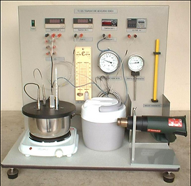
General
This bench top unit is used for studying temperature measurement of several commonly used devices as well as understanding related principles.
Heat sources and means for calibration and accuracy comparison of the different devices is provided.
Learning program
Physical principles of each device
Calibration techniques
Lead and conduction errors
Dynamic response
Errors
Incorrect applications
Humidity influence
Technical Data
Primary temperature sensing devices
Platinum resistance thermometer -49.9oC…199.9oC x 0.1oC res.
Thermistor 0…..100 oC x 0.1oC resolution
Thermocouple Type K – NiCr/NiAl -75...120 oC x 0.1oC resolution
General industrial temperature measuring devices
Bimetallic thermometer 0…..200 oC
Vapour pressure thermometer 20….150 oC
Mercury glass thermometer 0……150 oC
Surface temperature indicator strips ……..250 oC
Wet and Dry bulb thermometer
Heat Sources
Hot plate with thermostat and stainless steel pot
Hot air blower with thermometer stand
Ice pail
Miscellaneous
Millivoltmeter
Digital readout for resistance thermometer
Digital readout for thermistor
Digital readout for thermocouple
Services
220/240V AC
Dimensions
W650 x L750 x H750mm

FLOW MEASUREMENT APPARATUS
General
This is a bench top self contained water circulating unit for studying the various flow measuring instruments including primary flow measuring devices.
The flow measuring instruments are connected in series and all except the measuring tank are arranged on a waterproof panel.
Measurement of flow by a primary flow measuring devices is by coefficient of discharge which is determined from a pressure drop across the device and its flow rate. The flow rate is obtained from a water meter reading and a stop watch. The pressure drop is measured by differential pressure using manometers. Pressure tapping is by small ball valves with quick connection. The water tanks are behind the panel.
The flow rate is varied by a flow control valve.
The water tank and the pump are situated behind the panel.
Technical Data
Pump 0.37kW
Maximum Flow Rate Over 8L/min
Maximum pressure Over 18m water
Storage tank approx 60L
Primary flow measuring devices in clear plastic”
Venturi meter 29mm dia.17mm throat with 21o taper and 14o outlet taper
Orifice meter 20mm dia on 29mm tube
Pitot tube on 19mm tube
Other flow measuring devices
Water meter & stop watch
Rotameter up to 75 L/min
Measuring tank 40 L
Differential Pressure Measurement
Water manometer 8 tubes – 950mm x 1mm graduation
Power Supply 220/240 AC
Training Program
Comparison of differential pressure at various flow rates for:
-
Venturi
-
Orifice
-
Pitot tube
-
Variable area flow meter
Determination of coefficient of discharge for:
-
Venturi
-
Orifice
-
Pitot tube
Comparing flow rates from :
-
Water meter
-
Variable area flow meter
-
Measuring tank
Optional Items
HF 013 ISA nozzle on 29 mm diameter tube.
HF 031 Differential pressure sensor and indicator. 0-250 cm water.
HF 235-050 Computer Interface. This includes sensors, analog to digital signal converter with software for data display and analysis by computer.
HF 010 Flow sensor and indicator.
Other flow measuring devices can be supplied on request.

ANALYTICAL PROCESS CONTROL
General
The analytical process control system demonstrates the control of the quality of industrial and waste water. It combines chemical procedures with applied principles of control engineering. The mobile laboratory unit is dimensioned in away to allow experiments without neglecting the characteristics if industrial plants. Neutral water is mixed with diluted sodium hydroxide and the resulting ion load is measured. The addition of diluted sulphuric acid neutralizes the solution. Controlled aereation changes the oxygen content. Another experiment controls the redox potential of water using diluted iodine solution. All processes are equipped with extensive instrumentation and are controlled by industrial controllers. Transparent reaction tanks enable the processes to be observed
Training Program
-
Simulation of a salt load by addition of sodium hydroxide via a conductivity control system
-
pH value control of the solution using sulphuric acid
-
Change in the oxygen content by means of controlled aereation with compressed air
-
Control of the redox potential via the addition of diluted iodine solution
-
Monitoring and control of industrial waste water
-
High quality instrumentation in accordance with industrial standards
-
Four completely independent control loops
-
Use of industrial monitoring pumps
Technical Data
Chemicals: Sodium Hydroxide NaOH 2%
Sulphuric acid H2SO4 2%
Iodine solution ratio H2O:I 100:1
Metering pumps: Max. 1.7 Ltr/h
pH single rod measuring sensor 1…12pH
Conductivity sensor with integrated PT-100 temperature sensor: 0.01…20mS/m
Oxygen sensor: 0…60mg/ltr 02
Redox measuring electrode: 0…1000mV
Universalcontroller, microprocessor based
Multi channel recorder: 6 channels
Specification
-
Analytical process control system to monitor and modify industrial waste water
-
High quality instruments and control equipment for conductivity measurement, pH-value control, oxygen enriching, redox potential control.
-
pH-value single rod measuring sensor 0…12pH
-
Oxygen sensor 0…60mg/ltr O2
-
Industrial redox measuring electrode 0…1000mV
-
Microprocessor controlled universal controller
-
6-channel recorder
-
Transparent reaction tanks
-
Sturdy steel frame with castors
Scope of delivery
1 Analytical process control system
1 Instruction manual
Dimensions
L1800 x W700 x H 1850 mm
Approx. 150kg
 Analytical Process ControlLegend 1 Control panel with industrial controllers and recorders 2 Oxygen content measuring instrument 3 Reaction tank 4 Conductivity measuring instrument 5 Metering pumps 6 Chemical tanks 7 Reaction tank 8 Measuring probes 9 Collecting tank 10 Compressed air connection |
|---|
COMPREHENSIVE PROCESS CONTROL
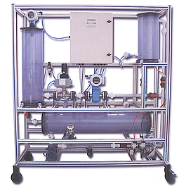
General
The Process Control and Instrumentation rig provides a self-contained process control system which is representative of many industrial systems that are used in the chemical, oil. Food, water and other process industries.
The rig is fitted with state-of-the-art intelligent process instruments and actuators which are networked via PROFIBUS PA and DP to communicate with a Programmable Logic Controller (PLC).
The controlling PLC can be configured to implement a number of different control strategies for flow and level control using cascade, feed-forward and multi-variable strategies.
The rig also provides separate level alarms and process and device temperature monitoring. Further, the control system is linked via an Ethernet Local Area Network (LAN) to a modern PC platform and gateway which provides modem Control and Data Acquisition (SCADA) monitoring and control of the process.
Asset management tools are also available on the PC workstation for calibration, diagnostics, predictive maintenance and other engineering instrumentation and actuation tasks.
Full specification will be provided on request
SINGLE PROCESS TRAINERS
 Flow Rate Control FcbThis unit is designed for automatic flow rate control using a calibrated diaphragm, a pneumatic valve, a differential pressure transducer and a PID controller Can be supplied with freely connectable inputs and outputs PID – Open Loop – Closed loop Tuning methods etc Available with supervisory software |  Level Control LcbThis unit is designed for automatic level control in a small tank using an electronic level transmitter, a pneumatic valve and a PID Controller Can be supplied with freely connectable inputs and output PID – Open Loop – Closed loop Tuning methods etc Available with supervisory software |  Pressure Control PcbThis unit is designed for automatic pressure control in a tank or in a pipe using an electronic pressure transmitter, a pneumatic valve and a PID controller. Can be supplied with freely connectable inputs and output PID – Open Loop – Closed loop Tuning methods etc Available with supervisory software |
|---|---|---|
 Temperature Control TcbThis unit is designed for automatic temperature control of a liquid using a heat exchanger, a hot water source, a pneumatic valve and a PID controller. Can be supplied with freely connectable inputs and output PID – Open Loop – Closed loop Tuning methods etc Available with supervisory software |  pH Control pHcbThis unit is designed for the automatic control of pH in a small reactor, using PID Controller adjusting the flow rate of the acid solution Can be supplied with freely connectable inputs and output PID – Open Loop – Closed loop Tuning methods etc Available with supervisory software |  Multi Process Stand MpbThis unit is designed for the automatic control of flow rate, level, temperature and pressure by using the same control unit but modifying the hydraulic circuit Includes supervisory software |
PC CONTROLLED SINGLE PROCESS

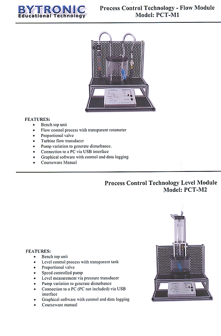
MULTI PROCESS TECHNOLOGY
FEATURES
Control of Discrete Processes
PID Control
Temperature, Level, Pressure and Flow Control
Graphical monitoring of real time processes
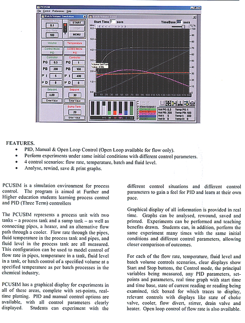
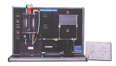
The PCT-100 Process Control Technology unit is a bench top unit that represents a system typically found in the process industry. Consisting of the Process Module and a Control Console with a Power Supply, together with a comprehensive interactive control program. The software has been developed to act as an inclusive PID teaching tool and provides historical data trending features. The Control Console has a representation of the Process Module on the front and includes fault switches.
Liquid contained in a Sump Tank is pumped around the process unit into a Process Tank the Flow rate, Level, Temperature and Pressure can be controlled. Sensors are used to determine the Pressure and Level in the process tank and a sensor in the flow pipe for the Flow rate with FT 1000 temperature sensors to determine the temperature of the liquid in the Sump and Process Tank and a magnetostrictive sensor is used to measure the Level. Forced air cooling is used to cool the liquid in the system. In addition to supplying this data to the controller, it is also represented on LCD units on the Process Module. Two proportional valves are used to control flow into and out of the process tank, a manually adjustable needle valve is used to add disturbances to the system and a pressure relief valve fitted for safety.
The Control Console contains connections to allow either PC (USB) and PLC control or a PID controller.
Exercises for the PCT-100 begin with setting up and executing a process cycle, through to optimising the PID controllers by estimating P, PI and PID parameters using Ziegler Nichols process reaction curve or ultimate cycle methods. Formulation of problems and resulting solutions coupled with bench-marking are manifest through tutorials.

CD ROMS/DVD INTERACTIVE
Please note that these programs are predominantly imperial as they were produced for the US market by the Instrument Society of America, now the Instrument Society in Automation which is the most prestigious player in this field
More than 6,000 corporate customers have chosen ITC’s iKNOW online and Activ™ CD-ROM training over the past 20 years.
Our courses have been developed by subject matter experts with substantial experience in
actual industrial environments, so they understand how the real world - your world - works. They’ve put together a curriculum that is:
Results-driven – Specifically engineered with the capabilities and
limitations of the plant environment in mind, so you get the most out
of every minute.
Interactive – Courses use animation, graphics, audio and
interactive exercises to keep your people engaged and on track.
Comprehensive – There’s pre-testing, final exams and practice sessions
that use a variety of formats to reliably assess your employees’ grasp of
subject matter.
Trackable – Our systems make it easy to monitor and manage the
progress of all your employees.
Easy to access – No proprietary plug-ins are required. ITC offers courses
online as well as through other delivery methods, so you can train
anyone, anywhere, any time.
Lessons include: (Click here for more information)
-
Gate Valve Repair
-
Globe & Control Valve Repair
-
Principles of Process Analysis
-
Spectroscopic Aalyzers
-
Gas Chromatographs
-
Air & Water Analysis
-
Process Sampling Systems
-
Body Types & Trin
-
Actuators & Positioners
-
Body & Trim Maintenance
-
Actuator & Positioner Maintenance
-
Controller Tuning
-
Smart Transmitters
-
Single Loop Digital Controllers
-
Distributed Control Fundamentals
-
Maintaining Distributed Control Systems
-
Pressure & Temperature Transmitters
-
Flow Transmitters
-
Leel & Weight Transmitters
-
Transducers, Annunciators, Recorders
-
Electronic Controllers
-
Pressure Measurement
-
Flow Measurement
-
Temperature Measurement
-
Level Measurement
-
Single Loop Control
-
Multiple Loop Control
-
Calibration Principles
-
Calibrating Pressure & Differential Pressure Instruments
-
Calibrating Temperature Instruments
-
Calibrating Flow Instruments
-
Calibrating Level Instruments
-
Personnel Safety
-
Working with Hazardous Materials
-
Instruments in Hazardous Environments
-
Interpreting Process Control Diagrams
CONVERSION TABLES
 |  |  |
|---|---|---|
 |  |  |

